|
 |
 |
 previous page |
overall view |
next page

01 |
02 |
03 |
04 |
05 |
06 |
07 |
08 |
09 |
10 |
11 |
12 |
13 |
14 |
15 |
16 |
17 |
18 |
19 |
20 |
21 |
22 |
23 |
24 |
25 |
26 |
27 |
28 |
13 – PCB machining tolerances (milling, V-scoring and drill holes)
If no tolerances are provided by the customer, the tolerances according to DIN 7168 medium shall apply.
13.1 – Permitted dimensional deviation without tolerance indication in mm (extract DIN 7168)
| |
Range of nominal sizes of untoleranced dimensions [mm] |
| Degree of accuracy |
> 0,5 – 3 |
> 3 – 6 |
> 6 – 30 |
> 30 – 120 |
> 120 – 315 |
> 315 – 2000 |
> 1000 – 2000 |
| fine |
± 0,05 |
± 0,05 |
± 0,1 |
± 0,15 |
± 0,2 |
± 0,3 |
± 0,5 |
| medium |
± 0,1 |
± 0,1 |
± 0,2 |
± 0,3 |
± 0,5 |
± 0,8 |
± 1,2 |
| coarse |
– |
± 0,2 |
± 0,5 |
± 0,8 |
± 1,2 |
± 2,0 |
± 3,0 |
very coarse
|
– |
± 0,5 |
± 1,0 |
±1,5 |
± 2,0 |
± 3,0 |
± 4,0 |
 |
 |
 |
 |
 |
 |
 |
 |
13.2 – Diameter tolerances
Non-metallized drill holes
Non-metallized drill holes must be differentiated from locating holes for automatic placement machines and testers, with close tolerance requirements and mounting holes for the assembly of PCBs and structural elements with standard tolerance requirements. Mounting holes are specifically dimensioned and have to be drilled in a single work procedure along with the metallized drill holes.
For all other non-metallized drill holes and drill holes that are not specifically identified, the tolerances of DIN 7168 medium shall apply.
Metallized drill holes
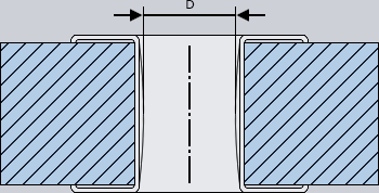
Unless otherwise defined in the order documentation, the following tolerances shall
apply for nominal diameters D: ± 0,1
In selecting a diameter, make sure that the land are selected accordingly, in order to obtain a sufficiently large annular ring.
 |
 |
Example:If you require a final diameter of 0,8 mm, the PCB manufacturer must take into account the metallization of the drill hole (see figure on the left). Depending on the surface, an addition of 0,1–0,15 mm, is calculated, i.e. the drill hole is drilled with a drill diameter of 0,95 mm. After applying the galvanic layers, a final diameter of approx. 0,85 mm is thus achieved. One crucial point is the via drill holes.
Negative example: A land of 0,5 mm with a hole diameter of 0,4 mm. If we proceed according to the calculation above with an additional 0,15 mm, then the finished PCB will only have an annular ring consisting of the metal in the drill hole. |
13.3 – Score tolerances
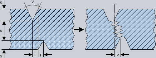
If the contours of the PCB are scored, the following tolerances will apply.:
| |
PCB thickness of
1 mm |
PCB thickness of
1,5 mm |
| Score angle V |
30° / 45° |
30° / 45° |
| Core thickness K |
0,3 ± 0,1 mm |
0,4 ± 0,1 mm |
Offset F
of each individual score
(reference to the nominal central line) |
± 0,05 mm |
± 0,05 mm |
Offset P
after separation
(reference to the nominal central line) |
± 0,15 mm |
± 0,15 mm |
 |
 |
 |

Distance of the pattern layout to edge of score
Distance too small
 |
 |
Distance correct

|
 |
PCB thickness 0,8 mm:
Xmin = 0,3 mm
PCB thickness 1,0 mm:
Xmin = 0,4 mm
PCB thickness 1,5 mm:
Xmin = 0,5 mm |
|
 |


