|
|
|
previous page |
overall view |
next page
01 |
02 |
03 |
04 |
05 |
06 |
07 |
08 |
09 |
10 |
11 |
12 |
13 |
14 |
15 |
16 |
17 |
18 |
19 |
20 |
21 |
22 |
23 |
24 |
25 |
26 |
27 |
28 |
27 – Test procedures in printed circuit board production
In circuit board production there are different test methods to test the finished circuit boards. Here is an overview of the relevant test procedures.
Visual Check
A visual check is always carried out. However, not all sources of errors can be identified in this way. Errors in plating-through-holes cannot be detected as well as hair cracks or micro-short closures. In addition, the visual control is flawed, as even obvious errors are often overlooked after a while.
Electric Test
The electric test tests connections from A to B. A distinction is made between Flying Probe (finger tester) and adapter test.
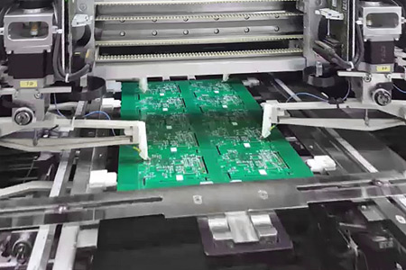
Flying Probe
Flying Probe is particularly suitable for tight pad distances, but is very time-consuming.
Therefore, Flying Probe is often used for samples and small series, where only one test program is required.
Fig. 1 – Flying Probe
 |
 |
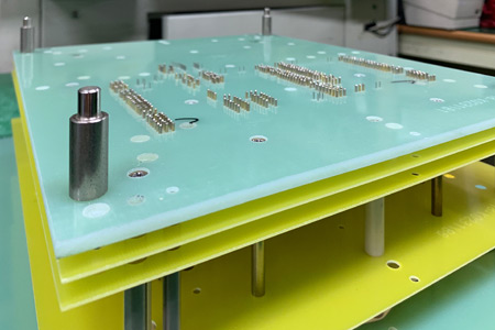
Adapter Test
It is more complex, as a needle adapter that is matched to the board is required. This allows all connections to be tested at once and only takes a fraction of the time compared to the Flying Probe. The electrical test also tests for faulty connections, e. g. B shorts due to etching errors.
Fig. 2 – Adapter single-side
 |
AOI Test
The AOI-Test – Automated Optical Inspection – is a control during production in the sense of a set-aside comparison. For this purpose, the circuit board is compared with stored images of the target state. After structuring, errors can be detected on internal and external layers. The use of the AOI usually depends on the track structures used.
High-Voltage Test
There are 2 different test methods for the High Voltage Test.
HV-DC-Test
The HV-DC test measures the insulation resistance between 2 tracks or measuring points. This can be done during the electrical test. For this reason, resistance limits are also specified here, where the system beats an alarm. The test voltage can be up to several hundred volts.
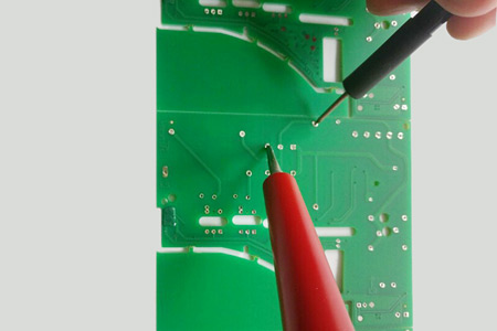
HV-AC-Test
In the HV-AC or dielectric test, the voltage resistance (insulation) between conductors is tested. For this purpose, a high voltage (>1000 V) is applied to the measuring points and checks whether there are breakthroughs and/or creep currents. It is customary to take samples and not to examine the whole lot of production.
Fig. 3, right – HV-AC Test
|
|
 |
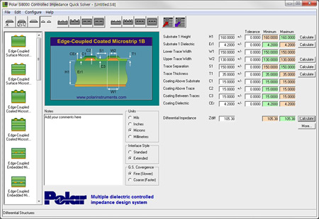
Impedance Control
The impedance control measures the apparent resistance (impedance) of conductor tracks. This is especially important for high-speed connections (high-frequency applications). For this purpose, the layers are simulated in advance and adjusted if necessary. The software also creates the necessary gerber data for the coupon, on which the impedance measurement is later performed. Measurements are usually made not on the circuit board itself, but on the coupon (Fig. 4), which is part of the production benefit and has the same circuit structure as the circuit board.
 |
|
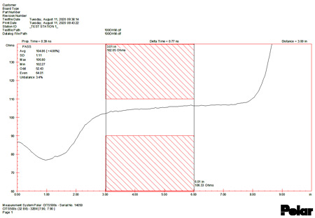
Fig. 4 – Simulation, test coupon and measurement results |
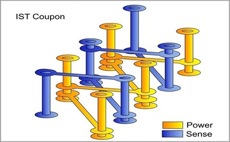
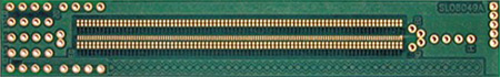
Interconnect Stress Test
The Interconnect Stress Test (IST) is a reliability test, so to speak an alternative to the temperature change or cycle test. Here, too, the test is performed on a special coupon. Advantage: High cycle rate, as the coupon can be heated and cooled very quickly, in a few minutes only. Disadvantage: Relatively expensive measuring system. Therefore, such tests are mainly used in areas where a very high level of reliability is required (aerospace, medical technology, etc.).
 |
|
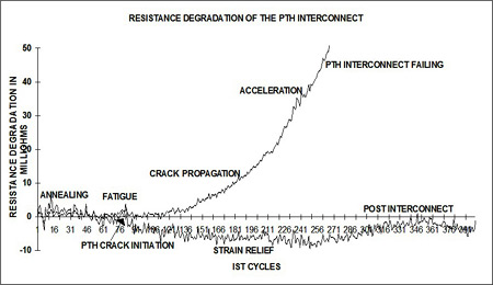
Fig. 5 – Functioning, test coupon and measurement results (pictures copyright by Polar Instruments) |
4-Wire Test
The four-wire measurement (4-wire test) is a resistance measurement for very small resistance values (< 0. 1 Ohm). This method is predominantly used for HDI multilayers, e. g. to detect copper defects in Micro-Vias. This method masks measurement distortions caused by conductive and transition resistors.
LaTest®
The LaTest® is also suitable for detecting copper defects in vias and lacing (Mouse Bites) on conductor tracks. For this purpose, a signal is given to the net to be tested and recorded again at certain measuring points. Errors lead to a phase shift of the signal and can therefore be detected. This process is also very complex and is only used for highly complex printed circuit boards.
|
|